Description
In our third lab, you and your partner will build a full adder, and then combine with another group to obtain a 2-bit ripple-carry adder.
You will not succeed if you do not read the following instructions. If you have a question, ask your TA.
Safety First
You are dealing with live power. Be mindful of the current and voltage you are supplying to the circuit. You should be supplying 5V and keep current (A) at around 9 or 12 o'clock. No drinks on the working surface.
Procedures
Find your lab partner. Then:
- Fix your input and output circuit if needed. Keep the input and output circuits on FAR ends of the breadboard, leaving much room in the middle for the logic circuit. Think about the necessary gates (integrated circuits), and the space you have on your breadboard.
- Make your breadboard neat if needed. Unnecessary long wires crowd your circuit. See the Important Notes section for details about this.
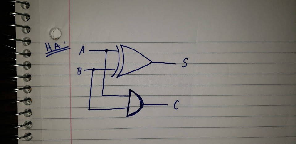
- Build a half adder using the logic schematic below.
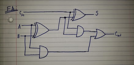
- Once the HA is complete, modify it to make it a Full Adder (logic schematic below).
- Once your Full Adder is complete (make sure to show your TA), you are ready to make it a 2-bit ripple carry adder. The schematic diagram for this 2-bit adder is below. To make it, you will need a second complete Full Adder. Bring your breadboard to a group that also has their Full Adder complete. Then, feed the CARRY OUT of one adder to the CARRY IN of the second adder, just like what was presented in lecture.
Important Notes
For your output circuit, you should use two LEDs of different colors (one representing sum -- one representing carry). This way, it is easier to tell them apart. After you link up with another group to create a 2-bit ripple-carry adder, be mindful of the necessary inputs and final outputs.
You will succeed in this lab if you ask your TA questions, refer to the schematics, and talk to your partner. Your TA is there to help you -- they don't bite.
Feel free to pull up this page, or the breadboard video, on a lab machine or your phone/laptop.
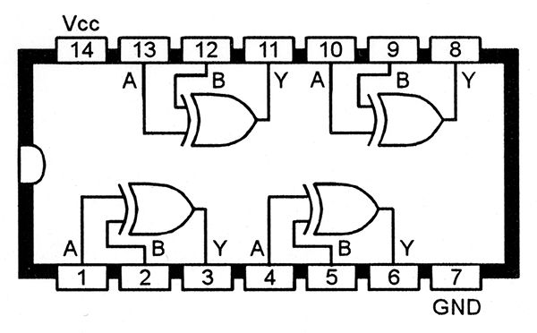
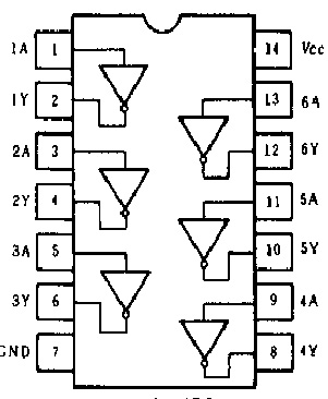
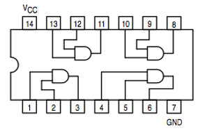
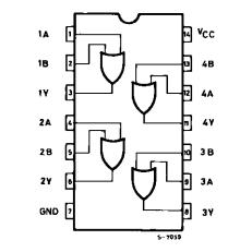
Be mindful of the notch on the integrated circuits. Counting counter-clockwise from the notch, pin 7 is ground, and pin 14 is power. This is standard across all 7400-series IC's.
REMEMBER: Always plug your integrated circuits into power (Vcc) and ground (GND) FIRST.
REUSE THE SAME INTEGRATED CIRCUIT: These 14-pin IC's have many logic gates in one!
It is good practice to keep your breadboard as clean as possible. Use short wires when you can. Your breadboard should not suffer from "spaghetti wire syndrome" -- this makes your circuit difficult for your TA to analyze.
74HC86 (XOR gate) pinout diagram
74HC04 (NOT gate) pinout diagram
74HC08 (AND gate) pinout diagram
74HC32 (OR gate) pinout diagram
Half Adder Logic
Full Adder Logic
2-bit Ripple-Carry Adder

Once you are finished, show your demo to the present TA, who will assign your grade out of five. Remember, you can continue to improve your circuit and show unlimited demos to the TA. Your TA will guide you toward receiving full points.
Teardown
Unplug your power supplies and place them on the middle table. Place all PSU wires in their respective boxes. Place wire containers in the large cardboard box (containing wires and breadboards). Any unused components should be put away.
Do not clear your breadboard, as you will use the input and output circuits for the next lab. Before you leave, place it on the shelf on your labeled piece of paper that you made in Lab #1.